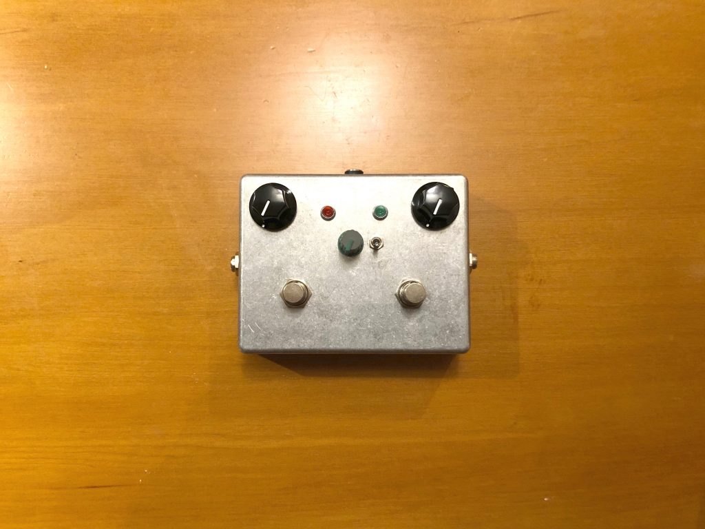
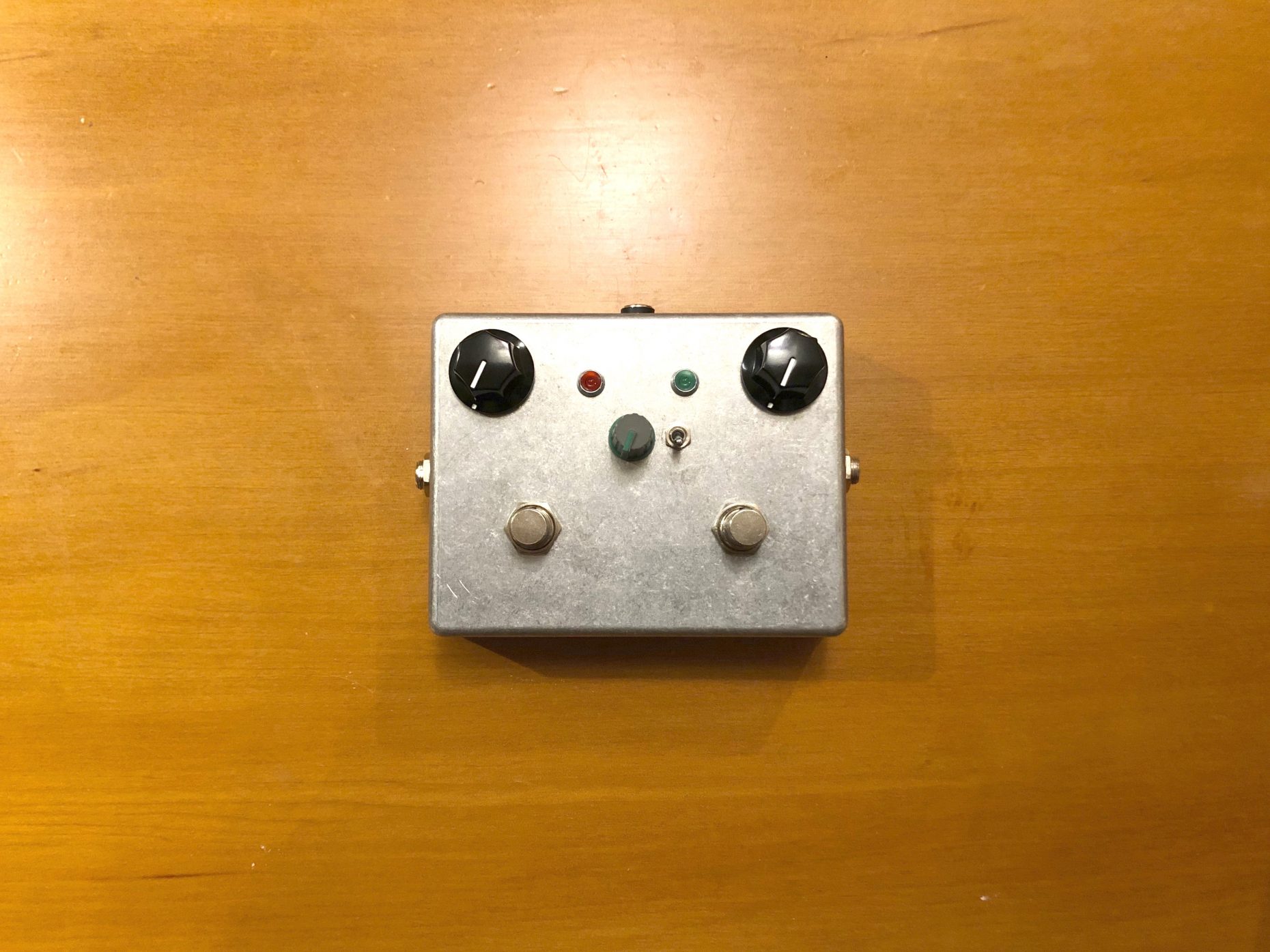
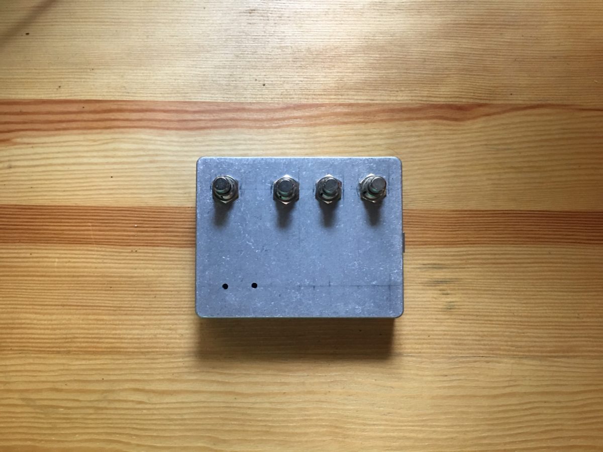
To keep myself busy during the 2020 quarantine, I decided to learn how electronic components affect audio signals and built a pedal for my electric guitar. The pedal I built is essentially a boost pedal made up of multiple circuits in one enclosure.
First is a boost stage, second is a saturation/EQ stage and third is an LED hard clipping stage.
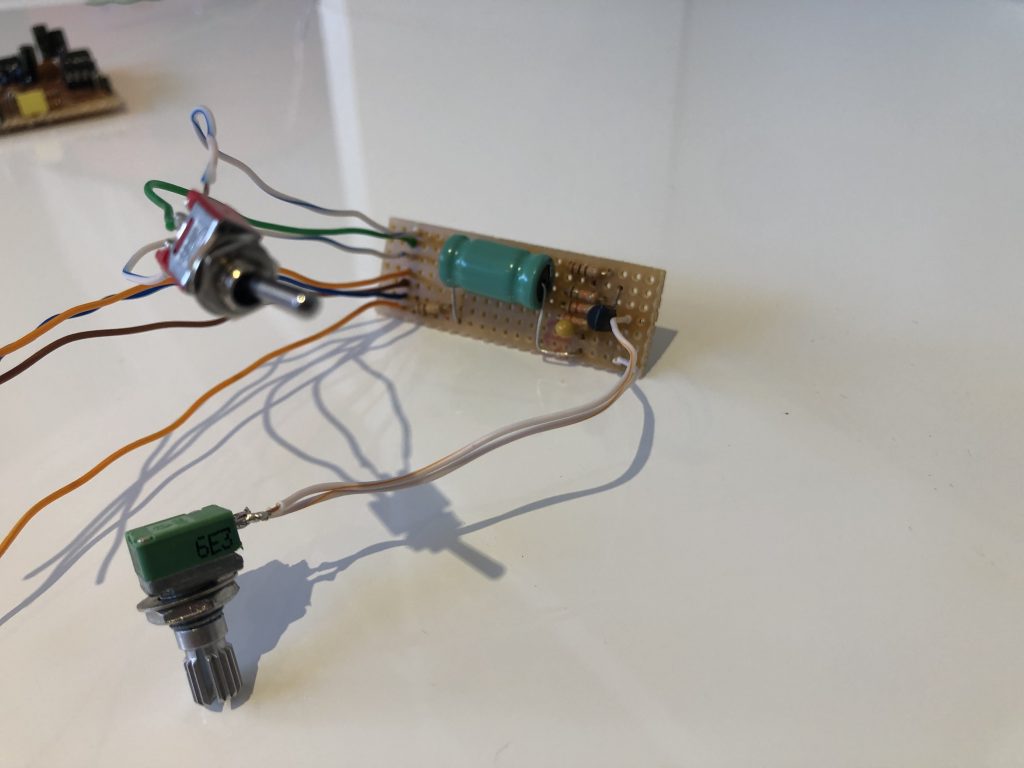
The current version of the above boost circuit has a few changes. I used different capacitors of the same value which made the signal cleaner, ditched the toggle switch and chose a fixed input resistance, then added a diode for reverse polarity protection.
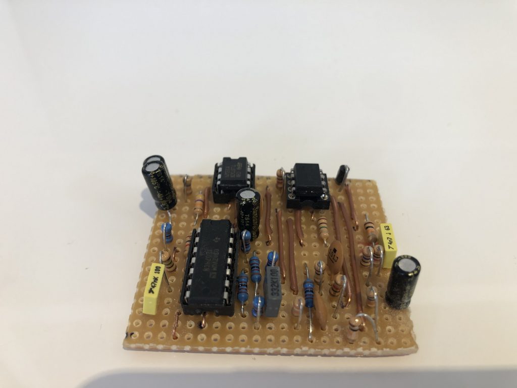
Most AC-DC converters do not provide pure DC power and usually have slight ripples of AC power which are audible. The best solution is to use isolated converters or converters designed for audio. To save some money, I built a power filter instead so that each pedal would receive less of the AC ripple. Should I choose to record, I will use a 9v battery which provides pure DC power but for now the power filters allow me to practice with minimal hum.
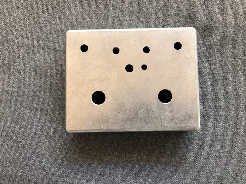
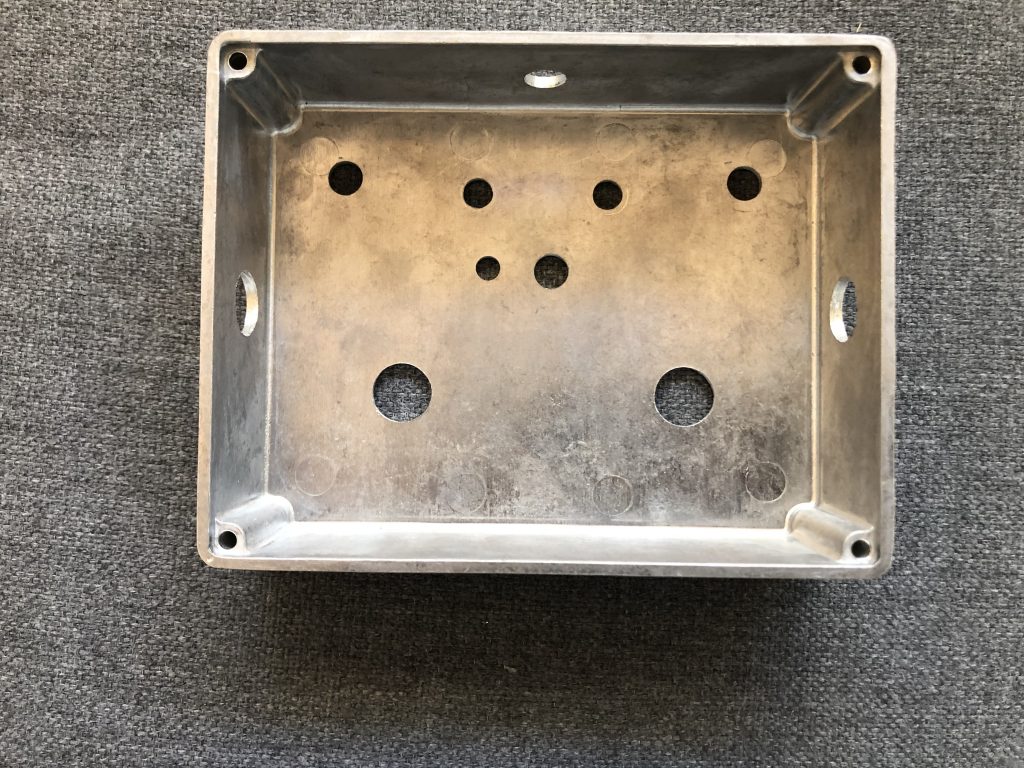
Next step is to measure and drill holes for all pots, switches, LEDs and connectors.
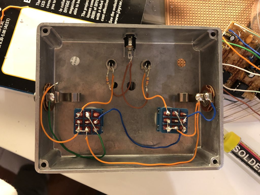
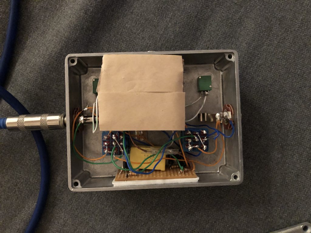
Above the 3PDT stomp switches have been wired in a way to allow signal to flow when only one or both circuits have been activated. It is true bypass and allows for signal to flow between both TS connectors without going through any circuits. The wiring also activates the LEDs and indicates which circuit is currently active. If I were to rebuild this pedal, I would consider adding a third 3PDT switch allowing me to change the circuit order rather than a fixed linear order.
